Connecting ESP32 to External Sensor BMP280
Hello, future engineers!!
Welcome again to my blog!
My name is Muhamad Fariz Ramadhan from STI 2020 ITB. I made this blog to help you guys out about embedded system especially setting up ESP32 to have some conditions. At this time, I am going to show you how connecting ESP32 as a microcontroller to external sensor.
*DON'T YOU KNOW??*
There are so many sensors in embedded system, each of it has main function to detect the conditions of their environment such as temperature, motion, humidity, warmth, and more.

So, now we're going to connect ESP32 to external sensor but in simple way first. We will only use BMP280, the sensor that could read temperature, pressure, and also altitude. Here is the tutorials.
STEP 1 : Required Hardware
 |
| BMP280 source : elekrtolead. |
1. ESP32 Development Board
2. Laptop / PC
3. Micro USB cable
4. BMP280 (soldered)
5. Motherboard
6. Jumper wires
STEP 2 : Required Software
1. Download and install Arduino IDE

You can download Arduino IDE from this link: https://www.arduino.cc/en/software and choose suitable version for your laptop / PC. After that, please install the app by following the instructions. You can check my other blog here for more information.
2. Open Arduino IDE and install BMP280 library
After Arduino get installed then we have to set up the app to suitable for BMP280
Go to Tools > Manage Libraries. Then, search "BMP280" and install the 2 of top; Adafruit and BMP280_DEV.

STEP 3 : Circuit time & Demonstration
1. Learn the concept
Basically, we're going to connect only 4 of 6 BMP280's pin to ESP32, Here is the schematic illustration.

2. Set up the circuit
From the illustration above, we can state that the situation of the circuit is:
- a. VCC connect to 3V3b. GND connect to GNDc. SCL connect to GPIO (in this tutorial, I'm using GPIO22)d. SDA connect to GPIO (in this tutorial, I'm using GPIO21)
If you make it, then the circuit would be look like this.
 |
| Condition 1 : Using jumper male to female |
or
 |
| Condition 2: Using jumper male to male |
3. Upload the code
Here is the code for this tutorial.
#include <Wire.h>
#include <SPI.h>
#include <Adafruit_BMP280.h
#define BMP_SCK (13)
#define BMP_MISO (12)
#define BMP_MOSI (11)
#define BMP_CS (10)
Adafruit_BMP280 bmp; // I2C
//Adafruit_BMP280 bmp(BMP_CS); // hardware SPI
//Adafruit_BMP280 bmp(BMP_CS, BMP_MOSI, BMP_MISO, BMP_SCK);
void setup() {
Serial.begin(115200);
while ( !Serial ) delay(100); // wait for native usb
Serial.println(F("BMP280 test"));
unsigned status;
//status = bmp.begin(BMP280_ADDRESS_ALT, BMP280_CHIPID);
status = bmp.begin(0x76);
if (!status) {
Serial.println(F("Could not find a valid BMP280 sensor, check wiring or "
"try a different address!"));
Serial.print("SensorID was: 0x"); Serial.println(bmp.sensorID(),16);
Serial.print(" ID of 0xFF probably means a bad address, a BMP 180 or BMP 085\n");
Serial.print(" ID of 0x56-0x58 represents a BMP 280,\n");
Serial.print(" ID of 0x60 represents a BME 280.\n");
Serial.print(" ID of 0x61 represents a BME 680.\n");
while (1) delay(10);
}
/* Default settings from datasheet. */
bmp.setSampling(Adafruit_BMP280::MODE_NORMAL, /* Operating Mode. */
Adafruit_BMP280::SAMPLING_X2, /* Temp. oversampling */
Adafruit_BMP280::SAMPLING_X16, /* Pressure oversampling */
Adafruit_BMP280::FILTER_X16, /* Filtering. */
Adafruit_BMP280::STANDBY_MS_500); /* Standby time. */
}
void loop() {
Serial.print(F("Temperature = "));
Serial.print(bmp.readTemperature());
Serial.println(" *C");
Serial.print(F("Pressure = "));
Serial.print(bmp.readPressure());
Serial.println(" Pa");
Serial.print(F("Approx altitude = "));
Serial.print(bmp.readAltitude(1013.25)); /* Adjusted to local forecast! */
Serial.println(" m");
Serial.println();
delay(2000);
}
4. Demonstrations
If your code already uploaded, then test the circuit. If it works, the serial monitor will look like this.
*D

Here is the video demonstration
Bonus :
EXPLORE : Use external monitor to see the result!
At this bonus section, I am going to show you how to use an OLED display to show the result from BMP280, not just from serial monitor.
1. Hardware and Software additional requirement
More requirement needed to do this exploration, those are:
1. OLED Display (In this tutorial, I'm using SSD1306)
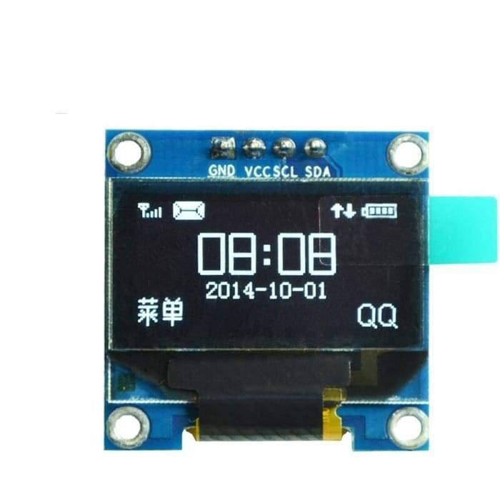 |
| source: Hallroad.org |
2. Install Adafruit SSD1306 Library
You can go to Tools > Manage Libraries, then search Adafruit SSD1306. Click Install > Install all.

2. Schematic Circuit
You just need to pair the pin name of BMP280 and on the LED for the circuit.
Here is mine.

3. Code
Here is the code, you can copy it and upload to your Arduino IDE.
#include <Wire.h>
#include <Adafruit_GFX.h>
#include <Adafruit_SSD1306.h>
#include <Adafruit_Sensor.h>
#include <Adafruit_BMP280.h>
#define SCREEN_WIDTH 128 // OLED display width, in pixels
#define SCREEN_HEIGHT 64 // OLED display height, in pixels
// Declaration for an SSD1306 display connected to I2C (SDA, SCL pins)
Adafruit_SSD1306 display(SCREEN_WIDTH, SCREEN_HEIGHT, &Wire, -1);
Adafruit_BMP280 bmp; // I2C
void setup() {
Serial.begin(115200);
// inisialisasi alamat bme280
bmp.begin(0x76);
if(!display.begin(SSD1306_SWITCHCAPVCC, 0x3C)) {
Serial.println(F("SSD1306 allocation failed or couldn't find a valid bme280"));
for(;;);
}
delay(2000);
display.clearDisplay();
display.setTextColor(WHITE);
}
void loop() {
delay(5000);
//read temperature and humidity
float t = bmp.readTemperature();
float h = bmp.readPressure();
if (isnan(h) || isnan(t)) {
Serial.println("Failed to read from bmp sensor!");
}
// clear display
display.clearDisplay();
// display temperature
display.setTextSize(1);
display.setCursor(0,0);
display.print("Temperature: ");
display.setTextSize(2);
display.setCursor(30,10);
display.print(t);
display.print(" ");
display.setTextSize(1);
display.cp437(true);
display.write(167);
display.setTextSize(2);
display.print("C");
// display pressure
display.setTextSize(1);
display.setCursor(0, 35);
display.print("Pressure: ");
display.setTextSize(2);
display.setCursor(30, 45);
display.print(h/1000);
display.print("kPa");
display.display();
}
4. Results
Here is the results. If your circuit and code uploaded properly then the OLED will show the temperature and pressure of the environment.

Here is the video demonstration.
That's it. Thank you guys.
Semoga bermanfaat!!
- Fariz STI'20


Komentar
Posting Komentar